Posted on: October 26, 2024
Welcome back! Yesterday, we met the 'quiet friend' of circuits—a simple resistor in Verilog-A. Today, we’re diving a little deeper into the structure of a Verilog-A module, the “anatomy” that powers its functionality. Imagine it like understanding the framework behind a favorite recipe. Instead of focusing on ingredients alone, we're looking at the entire process.
Understanding the Structure of a Module
A Verilog-A module typically includes several key elements:
- Library Includes: Always start by including the necessary libraries to access fundamental constants and disciplines.
- Module Declaration: This is where you define the module name and its ports.
- Parameter Declaration: Use parameters to customize your model, just like adjusting the size of a wrench to fit different nuts and bolts.
- Analog Block: Here’s where the magic happens! You define the behavior of your module, similar to how you would decide which tool to use for a task.
Step 1: Crafting a Verilog-A Model for an RC Circuit
Let’s take our resistor knowledge and add a new ingredient: a capacitor. When you connect these two in series, you get an RC circuit that’s fantastic for smoothing signals. Here’s how it looks in code:
`include "disciplines.vams" // Include fundamental constants
`include "constants.vams"   // Include Verilog-A libraries
module rc_circuit(p, n);        // Declare module with two ports 'p' and 'n'
  inout p, n;                   // Define 'p' and 'n' as analog ports
  electrical p, n, mid;         // Declare nodes 'p', 'n', and 'mid' as electrical

  parameter real R = 1k;        // Set resistance (1k ohm by default)
  parameter real C = 1n;        // Set capacitance (1 nF by default)

  analog begin
    I(p, mid) <+ V(p, mid) / R; // Current through resistor (I = V / R)
    I(mid, n) <+ ddt(C * V(mid, n)); // Current through capacitor (I = C * dV/dt)
  end
endmodule
This model builds a basic RC circuit. The resistor’s behavior is governed by Ohm’s law (current = voltage / resistance), while the capacitor’s behavior is a little more dynamic, responding to the change in voltage over time. It’s like a sponge filling up with water at a rate determined by the input current.
Step 2: Simulating the RC Circuit in Virtuoso’s ADE Explorer
Ready to bring it to life? Fire up ADE Explorer in Cadence Virtuoso:
- Create a new cell for
rc_circuitand paste in your Verilog-A code. - Design a schematic with a "pulse voltage source" connected to
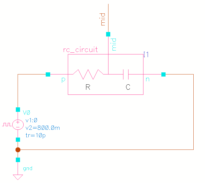
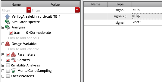
pand ground onn. The circuit should look like this! - Open ADE Explorer and set up a transient analysis to observe the capacitor charging and discharging over time. Here is the maestro view from ADE Explorer.
- Plot the voltage across the capacitor and the circuit current in Virtuoso Visualization & Analysis XL. After running the simulation, you should see the plots for capacitor voltage and current just as expected. With a resistance of 1 KΩ and a capacitance of 1 nF, the output voltage should nearly reach the supply voltage (VDD) after 5τ (time constants). As shown in the graph, by 5 µs, the capacitor voltage is almost at VDD. Interestingly, the capacitor voltage hits half of VDD at 0.693τ! (Fun fact: I once faced an interview question about when the capacitor voltage reaches half of VDD, and I blanked out! Unsurprisingly, I wasn’t selected. But hey, failure teaches you valuable lessons, right?)
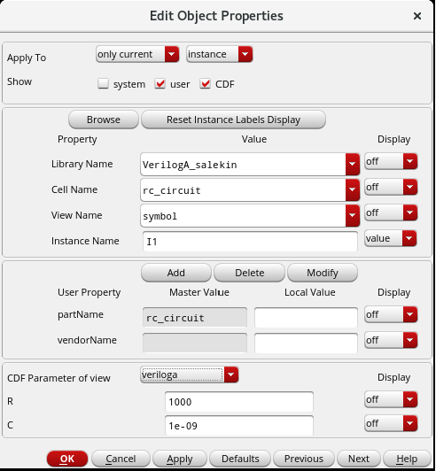
- I can already hear the question brewing in your mind: 'How can I tweak the values of my RC network here?' Great question! All you need to do is hit
qon therc_circuitschematic and chooseCDF Parameter of Viewasveriloga. Voilà! Now you can change the values of R and C to your heart's content. And do you know why these options are available? Oh, I know you guessed it! It’s because, while crafting your Verilog-A code, you cleverly used theparameterkeywords for R and C, setting default values of 1k and 1n respectively. This is how it all comes together in Virtuoso! - And finally, I changed the value of the Resistor to 2 KΩ. As expected, with the increased time constant, the capacitor voltage will take more time to reach to VDD. Check out the below plots to satisfy your insatiable mind 😉
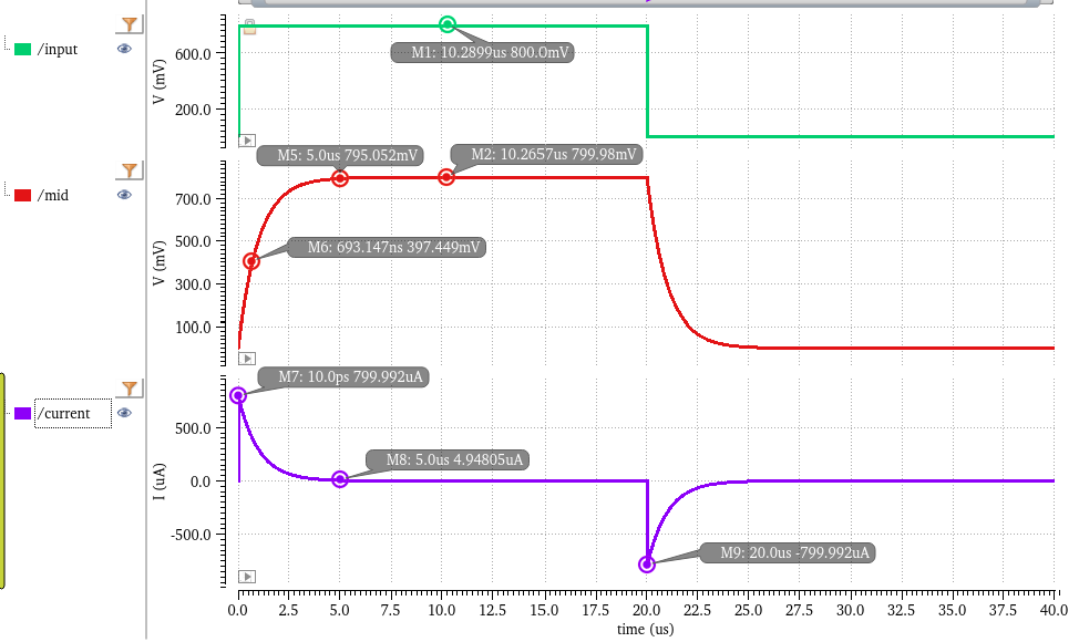
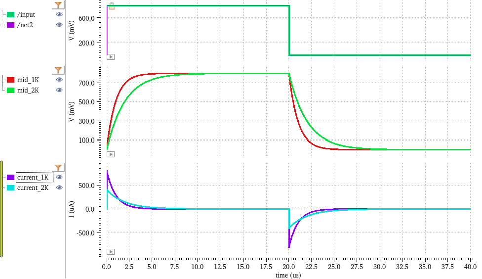
Watching the capacitor voltage rise and settle feels like observing a wave calm after the initial energy burst—a real-life view of electrical behavior.
Step 3: Understanding the 'Guts' of the Circuit
The 'guts' (core parts) here include the resistor and capacitor, each controlled by parameters R and C. We use Verilog-A's ddt() function to model the capacitor, where ddt() represents the derivative over time. Picture it as capturing the steepness of a hill as you go up or down; here, it measures how the capacitor’s voltage changes.
Wrap-Up
In Day 3, you’ve taken a closer look at how Verilog-A modules are structured and gained hands-on experience simulating a real circuit. Tomorrow, in Day 4, we’ll dive into understanding ports and electrical nodes in Verilog-A to get even closer to how these circuits connect and work together. Excited? Stay tuned!
