Posted on: October 25, 2024
Welcome to Day 2 of our Verilog-A adventure! If you're like me, every time you crack open a new code or model, you get a little thrill from seeing how something as basic as a resistor can make a world of difference in circuit design. But don’t worry, we’re going to ease into this. Today, you’ll create your first Verilog-A model for a humble resistor.
Step 1: Crafting Your Verilog-A Resistor Model
Before you ask, "What's the big deal with a resistor?", think of it as that calm friend at a party who quietly ensures everyone is having a good time. Without resistors, circuits would be like a wild dance floor after a sugar rush—utterly chaotic! They help keep everything in line, making sure the current flows just right and preventing any unexpected meltdowns.
`include "constants.vams"   // Include Verilog-A libraries
`include "disciplines.vams" // Include fundamental constants

module simple_resistor(p, n);
    inout p, n;               // Analog ports
    electrical p, n;          // Declare these ports as electrical signals

    parameter real R = 1k;    // Parameter for resistance value

    analog begin
        V(p, n) <+ I(p, n) * R;  // Ohm's law: V = IR
    end
endmodule
Boom! You just wrote your first Verilog-A model! If you felt a spark of joy, that’s because you’re now officially speaking the language of analog design.
Save the file as simple_resistor.va. You’ll want to remember this filename like you remember your phone’s PIN—it’ll come in handy soon.
Step 2: Simulation in Cadence Virtuoso
Now that you've got the magic code, let's see it come to life in Cadence Virtuoso. If you’ve ever worked in a lab, you know that this is the moment where you hook things up and cross your fingers.
- Launch Virtuoso.
- Create a new library—let’s call it something like VerilogA_salekin. Shhh! Don't get caught copying me!
- Write the Verilog-A code for your resistor model, and save it in a cell named simple_resistor.
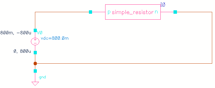
- Create a schematic with a DC voltage source and connect it to your new Verilog-A resistor.
- Open ADE Explorer, select DC Analysis, and plot the voltage and current. Run the simulation and enjoy that moment when your resistor behaves exactly as it should.
It’s like watching a slow-motion high-five between current and voltage. 🙌
This is how it should look like in Virtuoso Schematic view

Step 3: Simulation in Spectre (Terminal-Based)
Want to feel like a circuit magician? Time to summon Spectre. Terminal-based simulation is like driving stick shift—it’s not always necessary, but boy does it feel cool.
simulator lang=spectre // Sets the simulator language to Spectre
global 0 // Defines global node '0' as ground

I0 (net1 0) simple_resistor R=1000 // Instantiates resistor I0 with resistance of 1000 ohms, connected between 'net1' and ground
                                   // You can change the "R" value to any resistance value
                                   // Remember this line? "parameter real R = 1k;" You made "R" a varible.
                                   // Damn! This line makes more sense now
V0 (net1 0) vsource dc=800.0m type=dc // Instantiates a DC voltage source V0 with 800 mV, connected between 'net1' and ground

// (Start) Copy paste the bottom lines as it is for every spectre simulation
simulatorOptions options psfversion="1.4.0" reltol=1e-3 vabstol=1e-6 \
    iabstol=1e-12 temp=27 tnom=27 scalem=1.0 scale=1.0 gmin=1e-12 rforce=1 \
    vthmod=vthcc ivthn=300e-9 ivthp=70e-9 ivthw=0 ivthl=0 maxnotes=5 \
    maxwarns=5 digits=5 cols=80 pivrel=1e-3 sensfile="../psf/sens.output" \
    checklimitdest=psf vdsatmod=gds
dcOp dc write="spectre.dc" maxiters=150 maxsteps=10000 annotate=status
dcOpInfo info what=oppoint where=rawfile
modelParameter info what=models where=rawfile
element info what=inst where=rawfile
outputParameter info what=output where=rawfile
designParamVals info what=parameters where=rawfile
primitives info what=primitives where=rawfile
subckts info what=subckts where=rawfile
// (Stop) Copy paste the above lines as it is for every spectre simulation

save I0:p   // Saves the current through the positive terminal of instance I0 (the resistor)
saveOptions options save=allpub // Saves all public signals (voltages, currents) in the circuit
ahdl_include "~/VerilogA_salekin/simple_resistor/veriloga/veriloga.va" // Includes the Verilog-A file for the simple resistor model
You’ve got your testbench. Now, to run the simulation:
spectre testbench.scsCheck your results using Virtuoso Visualization & Analysis XL (viva). This is the part where you feel like a wizard in front of a crystal ball, except you're looking at graphs of voltage and current. Seriously satisfying.
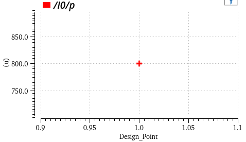
This is what is looks like in viva. As you can see the current is 800 uA, exactly what we expected to be!

Well! I know this code looks intimidating, isn't it? Fear not, you can generate the Spectre code from ADE directly! Here is how:

Well, you can see, you can generate the Spectre testbench as well! However it is important to know the syntax so that you can write the stimuli by yourself!
Wrap-Up
By now, you’ve not only written your first Verilog-A model, but you’ve also simulated it in two different ways: Cadence Virtuoso, and Spectre Terminal. Each step is like adding a new layer to your circuit-design superpowers.
In the next part, we’ll dig deeper into the Verilog-A universe, but for now, pat yourself on the back. You’ve come a long way from that blank editor screen.
