Posted on: October 24, 2024
Imagine This...
You're deep into an analog circuit simulation, adjusting parameters over and over again, and wondering—could there be a simpler way to model that circuit block without redesigning it every time? Welcome to the world of Verilog-A!
Welcome to the fascinating world of Verilog-A! If you've ever dabbled in analog circuit design, you know that capturing the complexity of real-world circuits can be a challenge. But fear not! In this post, we'll explore the wonders of Verilog-A, making it as engaging as a stroll through a bustling electronics market.
What is Verilog-A?
Verilog-A is a high-level modeling language designed specifically for analog and mixed-signal systems. It allows engineers to describe the behavior of electronic components in a way that's both intuitive and powerful. Think of it as a magic wand for circuit designers—turning abstract ideas into tangible simulations.
A Brief History
Introduced in the early 1990s, Verilog-A emerged as a response to the growing need for accurate analog modeling. Before its advent, engineers struggled with cumbersome and often inadequate tools. The arrival of Verilog-A was like discovering a hidden treasure chest; it opened up new possibilities for design and simulation.
Verilog, Verilog-A, and Verilog-AMS: What's the Difference?
To appreciate Verilog-A, it’s essential to understand how it fits into the broader Verilog ecosystem. Below is a comparison of Verilog, Verilog-A, and Verilog-AMS:
Comparison of Verilog, Verilog-A, and Verilog-AMS
| Feature | Verilog | Verilog-A | Verilog-AMS |
|---|---|---|---|
| Purpose | Used for designing digital circuits | Used for designing analog circuits | Used for designing circuits that have both analog and digital parts |
| Modeling Level | Creates models of digital systems | Creates models of continuous-time analog systems | Creates models that include both analog and digital components |
| Integration with Other Languages | Works well with SystemVerilog | Works with Verilog and SystemVerilog | Combines features from both Verilog and Verilog-A |
| Common Applications | Used in microprocessors and digital circuits | Used in amplifiers and filters | Used in systems that mix analog and digital signals, like radio frequency circuits |
| Simulators | Can be simulated using tools like ModelSim and VCS | Simulated with tools like Cadence Spectre | Simulated using tools that support both analog and digital simulations, like Cadence Spectre |
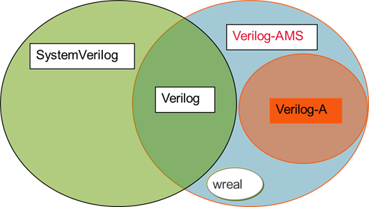
Venn Diagram Representation
Below is a Venn diagram illustrating the relationships between Verilog, Verilog-A, and Verilog-AMS:

Why Use Verilog-A?
Here are a few compelling reasons to embrace this powerful language:
- Simplicity: Verilog-A’s syntax is straightforward, making it easy for newcomers to grasp.
- Flexibility: It can be used to model a wide variety of components, from simple resistors to complex operational amplifiers.
- Integration: Seamlessly integrates with existing Verilog and SystemVerilog designs, allowing for mixed-signal simulation.
Imagine This...
Picture yourself in a lab, surrounded by oscilloscopes and circuit boards. You have an idea for a new analog filter. Instead of reaching for your soldering iron, you sit down at your computer and write a few lines of Verilog-A. Suddenly, your concept transforms into a dynamic model that you can simulate. The thrill of creation without the mess!
Getting Started with Verilog-A
Ready to dive in? Here’s a simple example to get you started:
    `include "discipline.h" // Include Verilog-A libraries
    `include "constants.h"  // Include fundamental constants

    module simple_resistor (p, n); // Module definition for a resistor with nodes p and n
        electrical p, n; // Declare electrical nodes p and n
        parameter real R = 1k; // Resistor value set to 1k ohms

        analog begin // Analog block for behavior definition
            I(p, n) <+ V(p, n) / R; // Current defined by Ohm's Law: I = V/R
        end
    endmodule // End of simple_resistor module
In this snippet, we define a simple resistor module. It captures the essence of Ohm’s Law in just a few lines—simple, right?
Tips for Writing Verilog-A Code
As you start your journey, keep these tips in mind:
- Comment generously: Your future self will thank you!
- Modularize: Break your code into smaller, reusable modules for clarity.
- Test frequently: Validate your models early to catch errors before they snowball.
Conclusion
Verilog-A is not just a tool; it's a gateway to exploring the rich landscape of analog design. With its intuitive syntax and powerful capabilities, you'll find yourself crafting intricate models that bring your ideas to life. So, grab your virtual toolkit and start your Verilog-A adventure today!
Stay tuned for the next post, where we’ll delve deeper into resistor design in Verilog-A and its simulation. Until then, happy coding!
